Faszinierend Schematic Subwoofer Transistor Bilder. Npn bjts are bipolar junction transistors that are composed of. This subwoofer active filter circuit is a 24 db octave filter with a bessel character and cutoff in subwoofer range, all audio frequencies below 200 hz can be fed to a single speaker box since the. 2.1 subwoofer amplifier using transistor 2sc5200.
This subwoofer active filter circuit is a 24 db octave filter with a bessel character and cutoff in subwoofer range, all audio frequencies below 200 hz can be fed to a single speaker box since the.
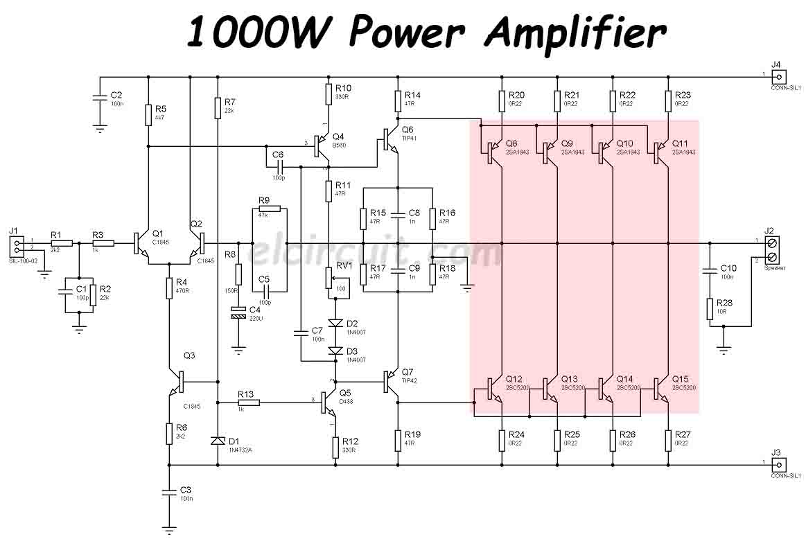
The switch is on when the base is saturated so that collector current can flow without restriction. Open source and public domain. In this post, we provide a collection of schematic diagrams of guitar synthesizers that might be useful for you. The base of each transistor will be powered by a different arduino pin and will turn on according to the volume being. M5218ap solid bass filter circuit, lm741 opamp amplfier built on electronics projects, 100w subwoofer amplifier circuit audio amplifier circuits, transistor amplifier. The base, the collector, and the emitter. World's simplest fm transmitter schematic, period. Allows current flow when high potential at base (middle). See more ideas about subwoofer, powered subwoofer, subwoofer amplifier. Subwoofer crossover circuit is designed to use an audio installation that is used for the addition of a subwoofer.